
Gravity Casting of Aluminum Brake Calipers - Reduction of a Rare Surface Defect Using DOE
The manufacturer of aluminum brake calipers was in the final phase of designing the casting process of a new caliper. Serial production was taking place on two semi-automatic prototype machines and on one fully automatic casting line. Ultimately, the prototype machines are to be replaced by subsequent automatic lines, however this must wait – the supplier estimated the lead time at 7 to 9 months. Therefore, until that time, the prototype machines must be used.
What does the process consist of?
We will focus on the prototype machines, which currently constitute 2/3 of the production capacity.
- Preparation of the casting mold: The mold, that is the casting form, consists of two halves. Each of them is covered with insulating coatings of different thickness – which allows control of heat removal and supports directional solidification. After installing the mold in the gravity die casting machine it is heated to the working temperature
- Manual pouring of the mold: The operator pours molten aluminum alloy through the gating system
- Gravitational filling and feeding of the casting: The metal spreads in the mold, venting of the system takes place and compensation of shrinkage by the riser
- Solidification: In the closed mold controlled directional solidification takes place – so that possible shrinkage porosity is led to the riser. Solidification is forced by cooling and different degree of insulation of the coatings mentioned in point 1.
- Opening of the mold and removal of the casting: After completion of solidification the mold opens automatically, and the operator removes the caliper and transfers it to cooling in water.
- Cutting off the riser and aging: The operator cuts off the riser and transfers the finished caliper to heat treatment in a special furnace – this increases the mechanical strength of the casting.
- Packaging and shipping: Then the castings are packed and shipped to the customer
What is the problem?
On the surface of the casting, always in the area of the base for machining (always the same place), a crack is formed. This is a defect which does not occur on any other type of calipers. It also does not occur on those calipers delivered to the customer by the competition. Additionally, it occurs extremely rarely and is visible only after the aging process. Over the period of 4 months about 150 calipers with a crack were found.
Despite introducing 100% inspection after the aging process and another 100% inspection during the process of packaging castings for shipment – the customer reports further complaints about this defect. After another one of them the customer demands to completely remove this defect – since the competition does not have these problems it means that it is possible to produce calipers without these cracks.
First approach to finding the root cause
The OpEx Group consultant was at that time carrying out a problem-solving project on another type of caliper. Asked for advice on how to approach this issue he recommended that technologists and engineers of the R&D department working on the development of the new process should try to intentionally produce the crack. If we can produce such a rare defect – we will quickly find the cause. Unfortunately, despite several days of trials, it was not possible.
In such situations, when knowledge about the process and about the product is very high (and here it was so), time and equipment for tests are available, and despite that the cause cannot be found it means one thing – we are dealing with an interaction. To learn about it, it is necessary to conduct a designed experiment.
We planned a DoE, the purpose of which was to produce the crack
Factors and levels selected for the experiment:
- Machine 1 vs 2: The problem of cracks concerned only prototype machines. 84% of bad parts returned by the customer came from machine no. 1. However, this does not mean that we are sure that the problem is the machine – see factor B.
- Mold M6 vs M5: Mold M6 produced 78% of bad parts returned by the customer. After checking it turned out that mold M6 was always mounted on machine 1. Thanks to factors A and B we will find out whether the problem is the machine or the mold or maybe their combination. Mold M5 did not produce any bad part and will be the second level of testing.
- Thickness of the insulating layer in the base for machining worn vs according to technology: As already described above casting molds are covered with a layer of coating of different degree of thermal insulation. This allows to enforce directional solidification – and thus avoid shrinkage porosity. There existed a theory that molds are used too long, because of which the worn coating may cause wrong temperature distribution and as a result cracks in the area of the base. We will test perfectly coated molds and then mechanically thin the insulating layer simulating wear.
- Solidification time 220s vs 260s: This factor is connected with factor E – directly it should not have influence on formation of cracks.
- Mold temperature 320 vs 400 °C: this factor was the main suspect. It was suspected that the mold due to lack of automatic pouring is overheated and this is the cause of cracks. The operator has the obligation to maintain mold temperature in the range 340–360 °C. Too long delay in pouring causes temperature increase – 400°C is very large overheating. Temperature 320 is the minimum temperature which was used at the beginning of production – at that time the customer did not report cracks. However, it caused formation of external porosity therefore it was increased to 340.
5 factors at two levels we can test in two ways: 25=32 runs and 25-1V=16 runs and this design of experiment we chose.
DoE results and root cause
In each run of the experiment, we produced 10 calipers – so during the whole DoE 160 pieces. We produced 102 good calipers but the remaining 58 had cracks in the base or even detachment of the entire area of the base for machining. This means that analysis of this DoE will tell us how to eliminate this defect. Y, that is the response from the experiment, is a simple proportion of bad parts in a given run to 10 – that is all produced in a given configuration. In seven runs of the DoE the fraction of bad parts was 0% in the remaining from 10 to 90% of bad parts. The Pareto chart below shows active effects.
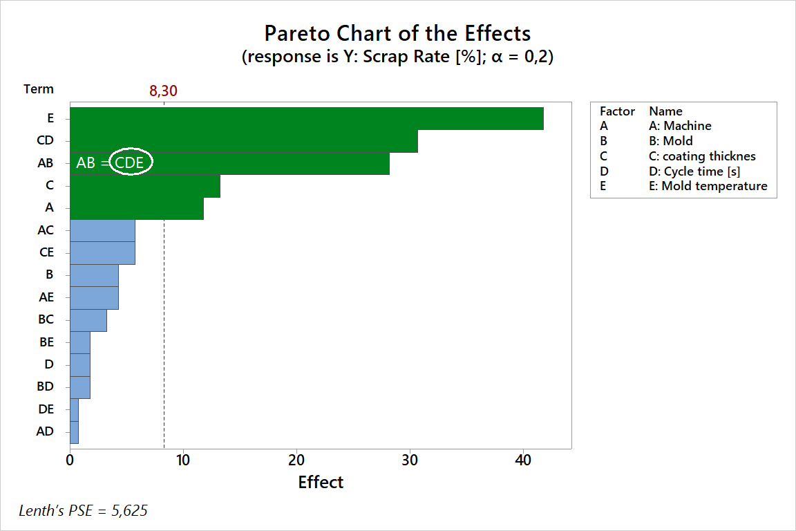
Taking into account sizes of effects (that is by how many percent we are able to influence the number of cracks) as active we mark those which are greater than 10%. Additionally, remembering about alias structure and due to illogical course of interaction AB as active we mark the 3rd order interaction CDE.
Summarizing, effects which created variation are:
Effect on Scrap Rate total [%]
A: Machine -11,79
C: Coating thickness 13,21
E: Mold temperature 41,79
C: Coating thickness*D: Cycle time [s] 30,71
C: Coating thickness*D: Cycle time [s]*E: Mold temp 28,21
R-sq R-sq(adj)
96,86% 95,30%
Using these effects, it is possible to explain over 95% of variation created in this DoE.
The only effect which is not in interaction with other factors tested in this DoE is factor A. Lack of interaction means that effect A will proceed in a similar way, regardless of how the remaining factors are set. The effect of machine 1 vs 2 is shown in the chart below.
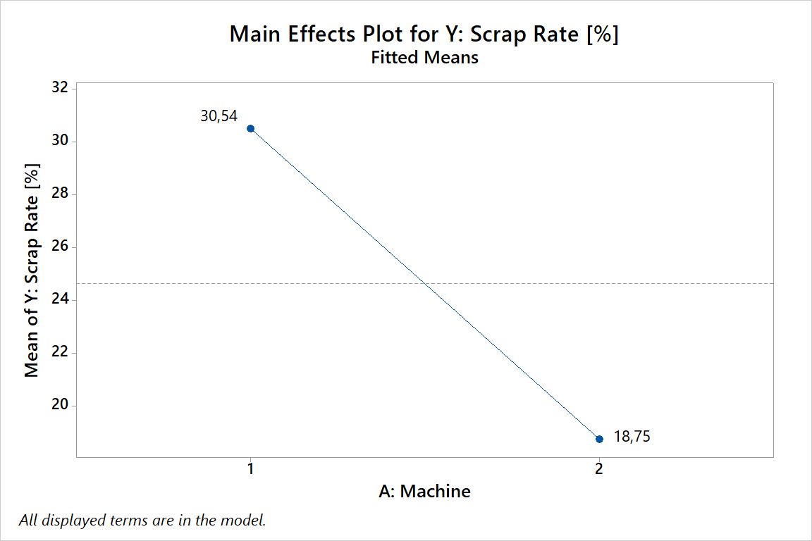
Effect A: Machine confirms that the difference in number of cracks can be attributed to machine 1, which during the DoE produced on average 30.54% of bad parts per run. Mold M6, which was also suspected of causing errors, turned out not to be significant.
The remaining factors C: coating thickness, D: solidification time and E: mold temperature are in active interaction, which means that analyzing their main effects does not make sense, because they will depend on the setting of each of these factors. The easiest way to see this is on the Box Plot shown below.
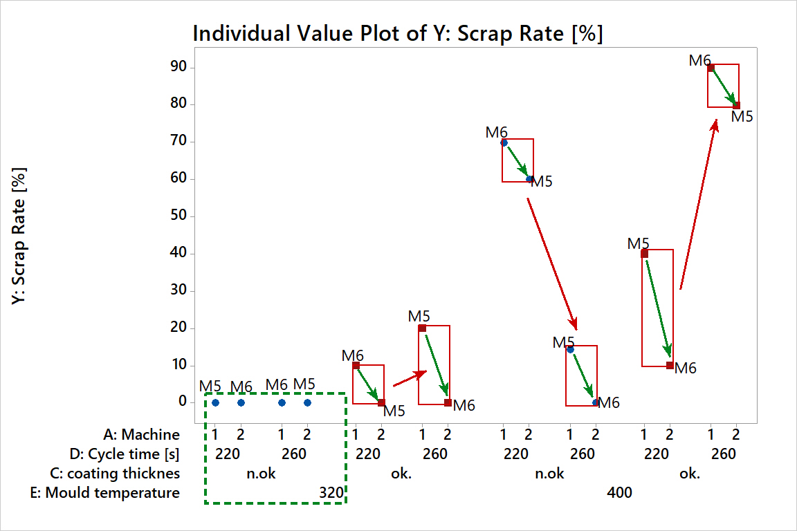
The main factor causing cracks is mold temperature. However it does not automatically mean formation of cracks. At the same time lowering this temperature does not guarantee that there will be no cracks. Only learning the interaction CDE shows that at reduced mold temperature and lower thickness of insulating coating we obtain 0 cracks. We can in such setting choose cycle time, there are also no differences between machines.
What was called a crack (visually it could look like that) was in reality a micro tearing out of not fully solidified casting from the mold. The established level of thickness of the insulating layer in this area of the mold was too high, which caused overheating of the casting. Ultimately it will be necessary to reduce insulation in this area, so that the casting is able to fully solidify.
On the chart above it can also be seen that it was machine 1 and not mold M6 that was responsible for creation of most cracks. The reason for this was the fact that due to location of the thermocouple in prototype machines, machine 1 showed underestimated actual temperature of the mold in the area of defect formation, hence it was more susceptible to overheating and thus defect formation.
ARTICLE IN PDF FORMAT
- If you want to learn how to plan, conduct, and analyze an experiment, check out How to Boil the Perfect Egg.
- If you want to see an example of an advanced DOE analysis, check out this article